
Autonomous Space Robotics Lab
Canadian Planetary Emulation
Terrain 3D Mapping Dataset
a100_dome
[Home] [Overview] [Hardware] [Details] [Downloads] [References]

Overview
This dataset consists of 95 laser scans obtained using a Clearpath Husky A100 at the University of Toronto Institute for Aerospace Studies (UTIAS) indoor rover test facility, located in Toronto, Ontario, Canada. This dataset was collected January 2011.
The UTIAS indoor rover test facility consists of a large dome structure, which covers a circular workspace area 40m in diameter. In this workspace, gravel was distributed to emulate scaled planetary hills and ridges, providing characteristic natural, unstructured terrain. Four large retroreflective sheets were placed outside the workspace to serve as easily-identifiable landmarks for ground truth localization.
Hardware Setup
 The Clearpath Husky A100 used to gather the dataset carried a number of payloads.
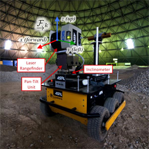
The relevant payloads for this dataset consisted of a vertically-scanning SICK LMS291-S05 laser rangefinder mounted on a Schunk PW70 pan-tilt unit to produce the 3D scans, and a Honeywell HMR3000 inclinometer to measure rover inclination.
The laser scanner was configured for a vertical angular resolution of 0.5°, and the scans were constructed by linearly interpolating the pan positions of the laser slices through the slow 360° scan sweep. Based on the manufacturer's specifications, the SICK LMS291-S05 has a range measurement standard deviation of 0.01m.
As depicted in the figure to the right, the scan reference frame was defined to be the laser rangefinder center, with +x pointing forward, +y to the left, and +z up. The inclinometer sat on the rover top plate, and the stereo camera was not utilized.
Dataset Details
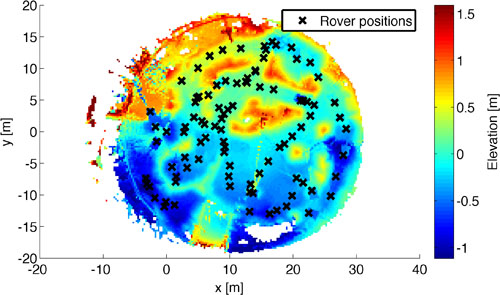
The 95 scans obtained for this dataset were collected with short motions conducted between each scan stop. This process encouraged overlap between scans, which should be beneficial for dense matching approaches. Since the terrain lay in the middle of an artificial dome structure, the scans were trimmed to remove the points that fell outside the workspace. The following image depicts an overhead view of the terrain, as well as the scan locations.

The ground truth sensor poses were provided by the identification of known landmarks outside the workspace. These consisted of four large retroreflective sheets mounted on the dome structure, which were utilized in a SLAM formulation to determine the six-degree-of-freedom sensor poses at each scan stop. Previous benchmarking experiments involving the same configuration demonstrated centimetre-level accuracy in translation, and half-degree accuracy in orientation [1]. By utilizing the same laser sensor for estimation as well as ground truth, the need for calibration to determine the ground truth pose offset was avoided. The ground truth reference frame was defined to be the same as the first scan pose.
Downloads
The a100_dome dataset is available at ftp://asrl3.utias.utoronto.ca/3dmap_dataset/a100_dome/.
[Download entire a100_dome dataset (zip) | Compressed size: 212MB, Extracted size: 928MB]
References
[1] Tong C and Barfoot T D. "A Self-Calibrating Ground-Truth Localization System Using Retroreflective Landmarks." In Proceedings of the IEEE International Conference on Robotics and Automation (ICRA), pages 3601-3606. Shanghai, China, 9-13 May 2011.