Motion-Distorted Lidar Simulation Dataset
Overview • Simulation • Dataset • Benchmark
Overview
The Motion-distorted Lidar Simulation Dataset was generated using CARLA, an open-source simulator for autonomous driving research. The implementation of the simulator is an open-source layer over Unreal Engine 4, a video game engine developed by Epic Games. We are not affiliated with CARLA or Epic Games. If you make use of this dataset, please make sure to give credit to the authors of CARLA.
Motion distortion refers to the rolling-shutter-like effect of present-day 3D lidar sensors, which operate by continuously spinning a set of stationary emitters and receivers. In applications such as self-driving, we have very fast moving sensor vehicles that make the distortion effect severe enough that it must be accounted for.
We capture the motion distortion effect in simulation by making each laser (equivalent to an emitter-receiver pair) activate once each simulation step. This means we simulate with an extremely small discrete timestep (0.05 milliseconds). The process is computationally expensive, taking several (real) hours to collect minutes of simulation. This results in data sequences with a motion-distorted lidar sensor producing 128000 measurements (maximum range of 120 meters) at a frequency of 10 Hz in simulation time.
Ground truth trajectories for all vehicles are also recorded. Unfortunately, there are no lidar intensity measurements.

We created this dataset because of our interest in dynamic (currently moving) object detection, an important problem for autonomous navigation. We required ground truth labels that distinguished lidar measurements (lidar points) as dynamic or static. While there are several public lidar datasets available with sequences of data in urban settings, none have ground truth to the extent we required. Simulated data will never be enough to replace real data, but we believe there is enough fidelity in CARLA to act as a benchmark for different dynamic object detection methods. We provide this dataset and carefully describe how we use it to benchmark our methods so that others may do the same.
Simulation
CARLA provides two maps, referred to as Town 1 (2.9 km of drivable roads) and Town 2 (1.9 km of drivable roads). We provide a 5 minute sequence of data for each map. For more information regarding CARLA, please visit their website.
Key points highlighting our configuration of CARLA:
- We used CARLA version 0.7.1.
- All vehicles, including the sensor vehicle, are driven with the provided autopilot implementation.
- There are 90 other vehicles driving on the roads in Town 1.
- There are 60 other vehicles driving on the roads in Town 2.
- Data is serialized and stored using Google Protocol Buffers (protobuf).
Notable limitations of the simulation:
- There are only vehicles (no pedestrians), using a source build of CARLA (version 0.7.1). This has been revised in more recent versions of CARLA. We will update our data in the future, but the simple collision models (i.e., ellipsoidal blobs) don't justify immediate priority.
- No lidar intensity measurements.
- Roads only have two lanes.
- No 4-way intersections, only 3-way.
Notable modifications we made:
- Each lidar frame (one revolution) is motion distorted.
- The lidar sensor closely simulates a Velodyne HDL-64E S3 by using relevant calibration values for each laser (rotational correction angle, vertical correction angle, vertical offset distance, horizontal offset distance).
- We provide the raw lidar measurements (range and bearing), rather than the coordinates in Euclidean space. Sample code for conversion to pointclouds is provided.
- We provide a unique object ID for each lidar measurement, corresponding to the object the measurement makes contact with. This unique ID currently only applies to vehicles. Everything else is considered as part of the stationary environment (benches, mail boxes, poles, etc.) and will return an ID value of 0.


Dataset
This section provides a high level overview of the data products provided. From reading this section you will understand what data products are provided and whether this dataset is of relevance to your work. For a more detailed description, particularly about how the data is stored or how to read the data, please see the downloadable manual.
Note: A frame of data refers to the collection of data over the 100 milliseconds it takes the lidar to complete a full revolution. It is not the same as the discrete simulation step, which is 0.05 milliseconds in length.
Important note: The dataset provides ftp download links. Some browsers no longer enable ftp links by default and you need to change the settings if you want to download using the browser. Using the wget command is an alternative to avoid the browser.
Sequences
|
Sequence |
Size |
Map |
Objects |
Length |
|---|---|---|---|---|
|
2.2 GB (8.7 GB Uncompressed) |
Town 1 |
90 Vehicles |
5 minutes (3000 frames) | |
|
2.2 GB (8.6 GB Uncompressed) |
Town 2 |
60 Vehicles |
5 minutes (3000 frames) |
Other Downloads
Data Products
Calibration
Calibration that persist for all sequences.
- [Lidar Laser Calibration] Required to convert the raw lidar data to pointclouds.
- [Sensor Vehicle to Lidar Transform] Transformation from the sensor vehicle frame to the lidar sensor frame.
Header data
This collection of data products persist for an entire sequence.
- [List of Unique Object IDs] A list of integer IDs that identify all vehicles in the simulation sequence.
- [Timestep] Discrete timestep of the simulation. This value is constant and will always be 0.05 milliseconds.
- [Channels Count] Number of channels (lasers). This value is constant and will always be 64.
- [Points Count By Channel] Number of measurements for each channel. This value is constant and will always be 2000.
Frame of Lidar Data (One Revolution)
Lidar data for one revolution, which is over 100 milliseconds of simulation time. Each of the 64 lasers will have 2000 measurements, for a total of 128000 measurements. For a single laser, the exact timestamps of the 2000 measurements can be interpolated for using the given start and end timestamps. Measurements are exact (no noise).
Note: The order of the measurements is row(laser)-major (i.e., 2000 measurements of one laser, followed by the next, etc.). The order of lasers corresponds to the row order of [Lidar Laser Calibration] values, which are provided in a csv file. This order is not by laser elevation angle.
- [Range] Range measurements in meters. Maximum range of 120 meters.
- [Rotation] Rotation (bearing) measurements in degrees.
- [Object ID] Object ID the measurement made contact with, a value of 0 if none.
- [Start Time] Timestamp of the first set of 64 measurements in nanoseconds.
- [End Time] Timestamp of the last set of 64 measurements in nanoseconds.
Frame of Vehicle Pose Data
The position and orientation (6 degrees of freedom) of all vehicles is given for every frame. Please see the manual for a more detailed description of the convention used. The timestamp of the [Current Position] and [Current Orientation] is the same as the [End Time] of the corresponding lidar frame. We also provide the position and orientation of the previous simulation step (0.05 milliseconds prior to the current timestamp, not to be confused with the previous frame timestamp) for those who wish to compute more accurate velocity values.
- [Current Position] Position of a vehicle with respect to the world frame in meters.
- [Current Orientation] Orientation of a vehicle with respect to the world frame in radians.
- [Previous Position] Position of a vehicle in the previous simulation step, with respect to the world frame in meters.
- [Previous Orientation] Orientation of a vehicle in the previous simulation step, with respect to the world frame in radians.
Benchmark
Description
This benchmark is concerned with measurement-wise (point-wise) labeling of dynamic (currently moving) vs. static (currently not moving) measurements (lidar points) over sequences of lidar data. We explain in this section how we use the dataset to benchmark our method in hopes that others may do the same.
Making comparisons to the ground truth on the object level requires a set of rules, such as what defines the object and what defines a correct detection. In contrast, comparisons on the measurement level is much easier and consistent.
The only source of possible inconsistency is that a speed threshold must be defined for determining for the ground truth whether an object is dynamic or static. We carefully explain in the manual how we define a dynamic object (i.e., the speed threshold) so that it is easily replicated.
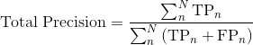
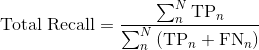
Computing Precision and Recall
We compute precision and recall in two ways: the total over the entire sequence and the average per lidar frame.
- A true positive (
 ) is a dynamic point that is correctly labelled as dynamic.
 - A false positive (
 ) is a static point that is incorrectly labelled as dynamic.
 - A false negative (
 ) is a dynamic point that is incorrectly labelled as static.
 - A true negative (
 ) is a static point that is correctly labelled as static.
Given  is the frame index and
  is the total number of frames in the sequence, the precision and recall over the entire sequence is computed as:
Given is the frame index,  is the total number of valid frames for precision computation, and
  is the total number of valid frames for recall computation, the average precision and recall per frame is computed as:
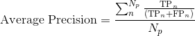
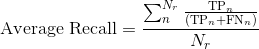
For the average computation, frames where the denominator term evaluates to 0 are ignored (e.g.,  ). This is why we distinguish the total number of frames for precision, , and recall, .
Using both the total variation and average per frame variation, compute precision and recall curves for all sequences. If a training dataset is needed (e.g., you require the use of the ground truth labels to tune your detection method), please indicate so.
License
MIT License
Copyright (c) 2019 Autonomous Space Robotics Lab at the University of Toronto
Permission is hereby granted, free of charge, to any person obtaining a copy of this software and associated documentation files (the "Software"), to deal in the Software without restriction, including without limitation the rights to use, copy, modify, merge, publish, distribute, sublicense, and/or sell copies of the Software, and to permit persons to whom the Software is furnished to do so, subject to the following conditions:
The above copyright notice and this permission notice shall be included in all copies or substantial portions of the Software.
THE SOFTWARE IS PROVIDED "AS IS", WITHOUT WARRANTY OF ANY KIND, EXPRESS OR IMPLIED, INCLUDING BUT NOT LIMITED TO THE WARRANTIES OF MERCHANTABILITY, FITNESS FOR A PARTICULAR PURPOSE AND NONINFRINGEMENT. IN NO EVENT SHALL THE AUTHORS OR COPYRIGHT HOLDERS BE LIABLE FOR ANY CLAIM, DAMAGES OR OTHER LIABILITY, WHETHER IN AN ACTION OF CONTRACT, TORT OR OTHERWISE, ARISING FROM, OUT OF OR IN CONNECTION WITH THE SOFTWARE OR THE USE OR OTHER DEALINGS IN THE SOFTWARE.