
Autonomous Space Robotics Lab
Canadian Planetary Emulation
Terrain 3D Mapping Dataset
[Overview] [Datasets] [Details] [Tools] [Related Datasets] [Credits] [Acknowledgements] [References]
Overview
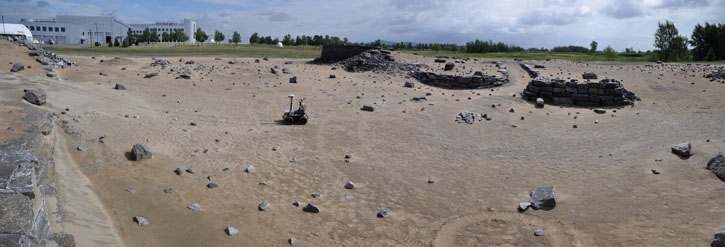
The Canadian Planetary Emulation Terrain 3D Mapping Dataset is a collection of three-dimensional laser scans gathered at two unique planetary analogue rover test facilities in Canada. These test facilities offer emulated planetary terrain in controlled environments, as well as at manageable scales for algorithmic development. This dataset is subdivided into four individual subsets, gathered using panning laser rangefinders mounted on mobile rover platforms. This data should be of interest to field robotics researchers developing algorithms for laser-based Simultaneous Localization And Mapping (SLAM) of three-dimensional, unstructured, natural terrain. All of the data are presented in human-readable text files, and are accompanied by Matlab parsing scripts to facilitate use thereof.
Datasets
Though the data were collected using three different rover platforms, these datasets share some common characteristics. In particular, 3D laser scans were obtained using a laser rangefinder mounted on a panning unit for all of the subsets. Due to the slow nature of the sensor, a stop-scan-go approach was taken where the 360° x 180° scans were obtained with the rover stationary. As a result, the rover poses and their associated measurements were easily segmented, providing no significant time synchronization issues to overcome in this dataset. Furthermore, all of the data have been post-processed into a common format, abstracting the data products from the hardware specifics.
The following pages describe the subsets obtained at the two planetary analogue test facilities. Though the data have been post-processed into a common format, it is suggested that the data from the two sites be considered separately for algorithmic development. This will allow for testing of the robustness of the algorithm to changing environmental conditions, as well as avoiding issues related to over-tuning. For example, the UTIAS data can be considered to be training data for development and tuning, while the data from the significantly larger CSA site can be used for validation.
Important note: The dataset provides ftp download links. Some browsers no longer enable ftp links by default and you need to change the settings if you want to download using the browser. Using the wget command is an alternative to avoid the browser.
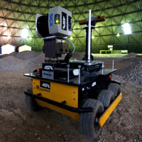
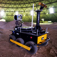
UTIAS Indoor Rover Test Facility (Dome)
- 95 laser scans
- Gravel hills in a 40m diameter circular workspace
- Clearpath Husky A100
- SICK LMS291-S05 laser rangefinder
- 6DOF ground truth poses obtained using known retroreflective landmarks
- [Click here for terrain imagery and dataset-specific details]
- [Download a100_dome dataset (zip)]
- 50 laser scans
- Gravel hills in a 40m diameter circular workspace
- Clearpath Husky A100
- SICK LMS291-S05 laser rangefinder
- Inter-scan visual odometry measurements computed using a Point Grey Bumblebee XB3 stereo camera
- 6DOF ground truth poses obtained using known retroreflective landmarks
- [Click here for terrain imagery and dataset-specific details]
- [Download a100_dome_vo dataset (zip)]
CSA Mars Emulation Terrain (MET)
- 102 laser scans
- Outdoor 120m x 60m sand and rock test site
- Modified MobileRobots Pioneer P2AT
- SICK LMS291-S05 laser rangefinder
- 3DOF ground truth positions and yaw obtained using a DGPS antenna array
- Roll and pitch provided by an on-board IMU
- [Click here for terrain imagery and dataset-specific details]
- [Download p2at_met dataset (zip)]
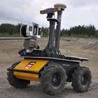
- 25 laser scans
- Outdoor 120m x 60m sand and rock test site
- Clearpath Husky A200
- SICK LMS291-S05 laser rangefinder
- Inter-scan visual odometry measurements computed using a Point Grey Bumblebee XB3 stereo camera
- 3DOF ground truth positions obtained using a DGPS antenna
- Orientation computed through manual alignment
- [Click here for terrain imagery and dataset-specific details]
- [Download a200_met dataset (zip)]
Datasets added after Data Paper review
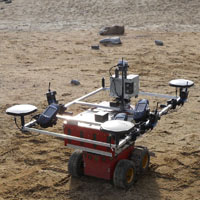
- 112 laser scans
- Outdoor 120m x 60m sand and rock test site
- Custom-built data collection platform
- SICK LMS111-10100 laser rangefinder
- Additional scan files including intensity information
- 3DOF ground truth positions and yaw obtained using a DGPS antenna array
- Roll and pitch provided by an on-board IMU
- [Click here for terrain imagery and dataset-specific details]
- [Download box_met dataset (zip)]
Data Description
In this section, we detail the data format common to all four subsets. For additional dataset-specific details such as hardware configurations, experimental considerations, and how the ground truth data were obtained, please refer to the individual dataset page links provided in the previous section.
Each dataset consists of a series of folders corresponding to the number of scans obtained. These folders contain space-delimited human-readable text files with the same file name as the folder, but distinguished by their file extensions. The coordinate frames and the file formats are detailed below.
Coordinate Frame Definitions
For clarity, we provide an image below illustrating the various coordinate frames that relate to the measurement data.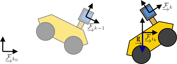
 , and the sensor frames at scan
  and scan
  are indicated by the
  and
and  symbols, respectively.
The levelled inclinometer reference frame is indicated by
  , along with the associated gravity vector,
  , where the underarrow indicates that the value has an associated direction.
Transformation matrices are utilized in this dataset to express the combination of translations and rotations.
For example, to transform a 3D point from  to
to  , a transformation matrix,
  , may be used in the following manner:

 is the vector from
  to point
  expressed in
  ,
,
 is the vector from
  to point
  expressed in
  ,
,
 is the rotation matrix from
  to
to  ,
and
,
and  is the translation from
  to
to  , expressed in
  .
.
Spherical Laser Data (.fcl)
A spherical coordinate laser file is composed of an 11-line header, and the laser points expressed in the sensor frame, .
The header provides details about the scan, including the timestamp, the scanning field-of-view and samples per scan line, the maximum and minimum range measurements, and the number of points in the scan.
A sample header is provided as follows:
            CSA Full Coverage Lidar raw spherical data; angles in degrees, lengths in meters

				    Wed Oct 13 14:16:27 EDT 2010

				    Horizontal FOV and Sample Size:

				    360.0 1080

				    Vertical FOV and Sample Size:

				    180.0 401

				    Min. and Max. Distances:

				    0.63 28.28

				    Nb. of points:

				    117840

				    Data [Azimuth(deg), Elevation(deg), Range(m)]:
The laser points then follow the header in the following format per line:
| azimuth [deg] | elevation [deg] | range [m] |
Cartesian Laser Data (.xyz)
The laser scans provided in Cartesian coordinates are also expressed in the sensor frame, , but do not contain a header.
The file format per line is simply
| x [m] | y [m] | z [m] |
Inclinometer Measurements (.inc)
Rover inclination was also measured to assist in processing the laser observations. The rover pitch and roll is expressed as a 3x3 rotation matrix, , which provides the rotation from the sensor frame,
 , to a frame,
  , where the +z direction corresponds to the opposite direction as the
gravity vector,
  .
Since heading measurements were unavailable, the heading rotation used to construct this rotation matrix was assumed to be zero.
Each rotation matrix is provided as a 3x3 space-delimited text file.
Odometry Measurements (.odo, .odounc)
In addition to the laser scans and inclinometer measurements, pose-to-pose transformation are provided for some of the datasets based on stereo visual odometry. Though these estimates were obtained using an alternate sensor, they have been transformed into the laser frame at each scan stop. That is, an estimate for the transformation from the previous scan frame, , to the current scan frame,
  , is provided as a 4x4 transformation matrix,
  , as well as its associated 6x6 covariance matrix,
  .
.
The definitions of  and
and  are
are

 is a three-parameter rotation axis parameterization [1].
The transformation that maps this parameterization to a rotation matrix,
  , is defined as

 , the skew-symmetric matrix operator, defined as

For consistency, the first scan folder also includes an odometry measurement, but it is simply the identity transformation, along with an associated covariance matrix with very large uncertainty values. These coarse pose transformation estimates can be used for initialization of more complex alignment algorithms. The transformation and uncertainty matrices are provided as 4x4 and 6x6 space-delimited text files, respectively.
Ground Truth Sensor Poses (.gt)
For evaluation, the ground truth sensor pose is provided as 4x4 transformation matrix, , which expresses the transformation from the rover sensor frame,
  , to the global estimate reference frame,
  .
Though some of these values were obtained using an alternate sensor, they have been transformed into the laser sensor frame at each scan stop.
In the case of these datasets, the global estimate reference frame was set to be the same as the first scan pose.
Each ground truth transformation matrix is provided as a 4x4 space-delimited text file.
Estimated Sensor Poses (.est)
For additional development, estimated poses are also provided in the same format as the ground truth sensor poses. These estimates were produced using the sparse-feature-based-batch alignment framework described in [2]. However, some of the scans could not be aligned using the framework. As a result, those estimates were simply set to their ground truth values, and indicated by the presence of a not_solved file in the scan directory.These estimates could be used for an initial guess for other alignment approaches, if the accuracy of the odometry measurements alone is insufficient. For example, a dense matching algorithm such as Iterative Closest Point (ICP) [3] could be used for further refinement. Each estimated transformation matrix is provided as a 4x4 space-delimited text file.
Helpful Tools
The following tools are provided to assist in utilizing the data.
Matlab Scripts
- loadDataset.m - Loads all of the files from a dataset into Matlab variables.
- loadFcl.m - Loads a spherical coordinate laser data (.fcl) file.
- loadXyz.m - Loads a Cartesian coordinate laser data (.xyz) file.
- loadInc.m - Loads an inclinometer measurement (.inc) file.
- loadOdo.m - Loads an odometry measurement (.odo, .odounc).
- loadGt.m - Loads a ground truth pose (.gt) file.
- loadEst.m - Loads an estimated pose (.est) file.
- deadReckoning.m - Computes a set of estimated pose transformations using the odometry measurements.
- fclToXyz.m - Converts from the spherical (.fcl) to the Cartesian (.xyz) laser data formats.
- xyzToFcl.m - Converts from the Cartesian (.xyz) to the spherical (.fcl) laser data formats.
- rotateXyz.m - Applies a rotation matrix to an xyz array.
- transformAndCombineXyzs.m - Transforms xyz points and combines them into a single array.
- plotTransformedXyzs.m - Plots the transformed xyz points.
Related Datasets
While this dataset focuses on 3D laser scans obtained in natural, unstructured terrain, similar datasets collected in a variety of environments are also available to the robotics research community.
A few datasets containing 3D laser data are listed below:
Credits
This dataset was the work of Chi Hay Tong, David Gingras, Kevin Larose, Tim Barfoot, and Érick Dupuis.
If you use the data provided by this website in your own work, please use the following citation:
Tong C, Gingras D, Larose, K, Barfoot T D, and Dupuis E. “The Canadian Planetary Emulation Terrain 3D Mapping Dataset”. International Journal of Robotics Research (IJRR), 2013. doi:10.1177/0278364913478897. (pdf)
Acknowledgements
The collection of this data would not have been possible without the support of many people.
In particular, we would like to thank Clearpath Robotics for the Husky A100 and A200 rover platforms used to gather the a100_dome, a100_dome_vo, and a200_met datasets. In addition, we would like to thank Jean-Philippe Roberge and Simon Rocheleau for their assistance in constructing the testbed and gathering the data for the box_met dataset.
Furthermore, the dataset collection was supported by a Natural Sciences and Engineering Research Council of Canada Collaborative Research and Development (NSERC CRD) / Canadian Space Agency Partnership Support Program (CSA PSP) grant in cooperation with MDA Space Missions.
References
[1] Hughes P C. "Spacecraft Attitude Dynamics." New York, John Wiley & Sons, 1986.
[2] Tong C, Barfoot T D, and Dupuis E. "3D SLAM for Mapping Planetary Worksite Environments." Journal of Field Robotics, Special Issue on "Space Robotics," accepted on October 18, 2011. Manuscript #ROB-11-0006, 2012.
[3] Besl P and McKay H. "A Method for Registration of 3-D Shapes." IEEE Transactions on Pattern Analysis and Machine Intelligence, 14(2):239-256, 1992.
